
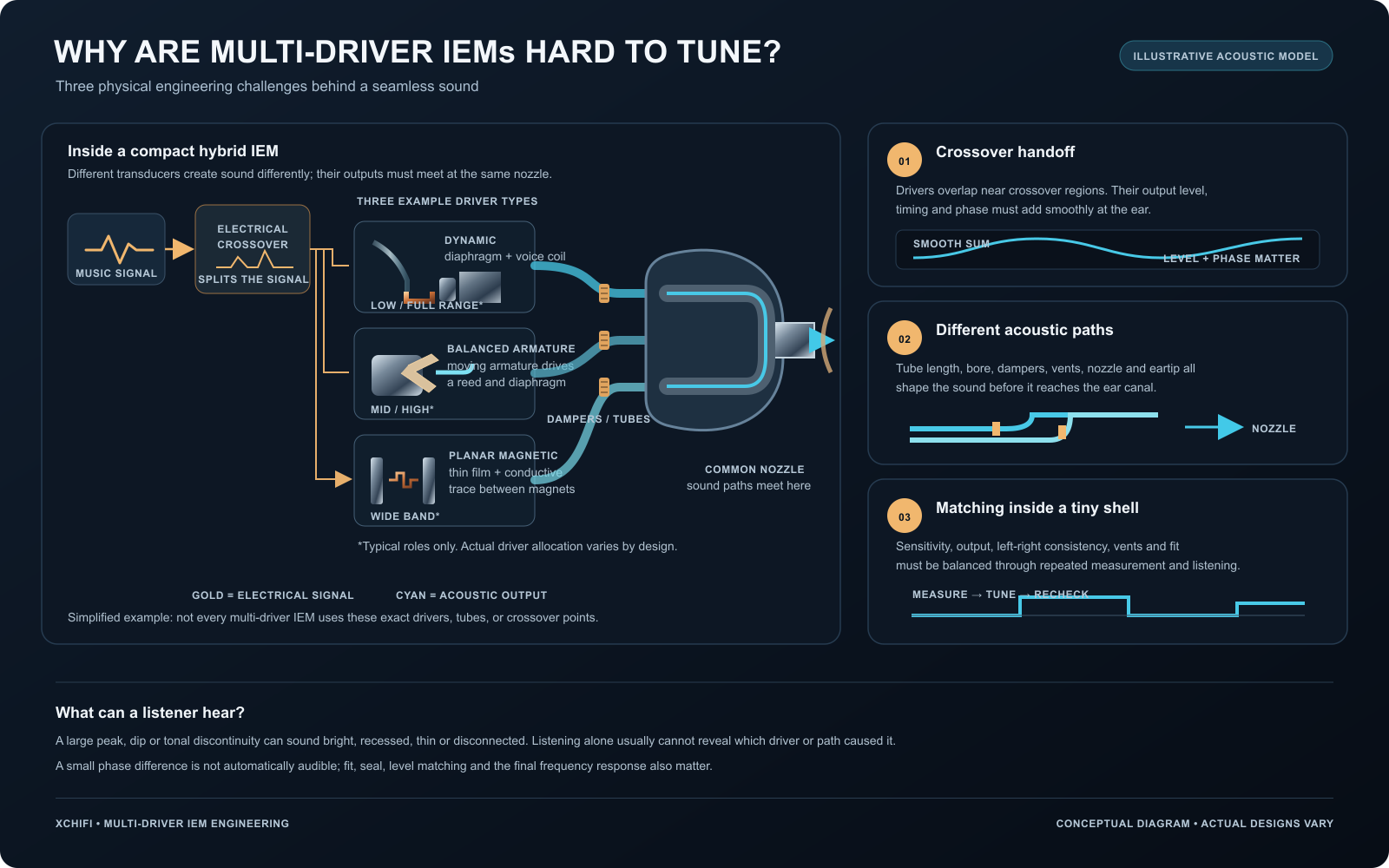
Can listeners hear when different drivers in an IEM fail to work together? Sometimes. A noticeable peak, dip or change in tone can sound bright, recessed, thin or disconnected. But listening alone usually cannot tell you which driver or internal path caused it.
A multi-driver IEM is not simply several drivers placed inside one shell. Dynamic, balanced armature and planar magnetic drivers use different physical structures to turn an electrical signal into sound. The real challenge is combining their outputs into one coherent result.
How Do Different IEM Drivers Work?
A dynamic driver uses a voice coil attached to a diaphragm. Current through the coil interacts with the magnet’s field, moving the diaphragm and producing sound. A planar magnetic driver places conductive traces on a thin diaphragm, which moves in a magnetic field. Balanced armature drivers use a small moving armature linked to a diaphragm.
Those mechanisms have different electrical and acoustic behavior. A driver’s sensitivity, useful frequency range and output level all affect how it should be integrated. The driver type alone does not determine whether an IEM will sound good: the final tuning and fit matter too. Yamaha explains the dynamic-driver voice coil and diaphragm, while FiiO describes the conductive traces and magnetic circuit in its planar IEM driver.
Challenge 1: Making the Crossover Handoff Smooth
The crossover divides the musical signal so each driver handles an intended part of the frequency range. But the drivers do not stop and start at perfectly separate boundaries. Their outputs overlap around crossover regions.
Engineers must balance each driver’s level, timing and phase so their sound adds smoothly. If the handoff is poorly matched, the combined response can develop a peak or dip. Depending on where and how large it is, a peak may sound sharp or forward; a dip may make part of the music seem recessed or weak.
Crossover design may involve electrical filters as well as acoustic components such as dampers and vents. Even a polarity change can alter the combined response, which is why the finished system has to be measured and tuned as a whole. Knowles’ application note shows how crossover polarity and nozzle acoustics can affect an earphone’s combined response.
Challenge 2: Managing Different Acoustic Paths
Sound from each driver must travel through the shell and reach the ear. Depending on the design, those routes may use separate or shared tubes, different openings, dampers or vents before meeting near the nozzle.
Tube length and bore, nozzle geometry, eartips and the seal in the ear can all change the measured sound. A path that looks like a small mechanical detail can affect the treble response. The paths therefore need to be designed and tested with the actual shell and eartip arrangement, not treated as empty space around the drivers. Knowles explains how nozzle and eartip acoustic channels influence high-frequency response.
Challenge 3: Matching Drivers Inside a Small Shell
An IEM has very little room. Drivers, tubes, crossover parts and vents must fit without blocking one another or compromising the shell’s shape and comfort. Engineers also need the left and right earpieces to behave consistently.
That means balancing output and sensitivity, checking the acoustic paths, and measuring repeated prototypes. A good result usually requires a cycle of measurement, listening and adjustment. The number of drivers on a specification sheet cannot replace that work.
Can Ordinary Listeners Hear the Difference?
Listeners can hear a sufficiently large change in the final sound: too much energy in one region, a missing part of the tonal balance, or a handoff that sounds uneven. They generally cannot identify the underlying cause just by listening. A perceived difference does not prove that a particular driver type, crossover or tube is responsible.
A phase difference by itself is also not automatically audible in every situation. What listeners hear depends on the combined response, the frequency involved, the fit and seal, and listening level. For a fair comparison, use the same eartips, make sure both IEMs seal properly, and match playback levels.
Do More Drivers Mean Better Sound?
No. More drivers provide designers with additional ways to shape the sound, but they also create more integration work. A well-tuned single-driver IEM can sound more coherent than a poorly integrated multi-driver model.
The goal is not to use the most drivers. It is to make every driver, crossover and acoustic path work together so the listener hears one balanced presentation.
Frequently Asked Questions
Can you hear a bad crossover in an IEM?
A large response dip, peak or tonal discontinuity may be audible, but listening alone usually cannot identify the crossover as its cause.
Do different driver types always need separate sound tubes?
No. Some designs use separate acoustic channels, while others combine outputs through shared paths. The right layout depends on the drivers, shell and tuning goals.
Are more drivers always better in an IEM?
No. Driver count is only one design choice. The crossover, acoustic paths, fit and final tuning determine how well the complete IEM works.
Explore our planar vs. dynamic IEM guide or learn how to create your own IEM.