
A kick drum can hit harder without making every bass note bigger. That is the useful question behind TINHIFI T6 bass tuning: where should the extra energy go, and what happens to the rest of the music?
TINHIFI describes balance as a design priority. For the T6 development example here, the brief is to preserve vocal clarity while exploring a stronger low end. A listener who prefers more bass has a different preference; that does not make either preference obsolete.
The T6 combines dynamic and planar drivers and offers interchangeable tuning nozzles, according to TINHIFI’s product guide. The following six steps explain the engineering decisions behind a bass-focused variation. They are not instructions to modify a retail pair. The illustrations use engineering material and acoustic principles; no measured T6 before-and-after frequency response is claimed.
This guide is part of IEM Acoustic Development. For more on enclosure design, explore Acoustic Chambers.
1. Check the seal before changing the tuning
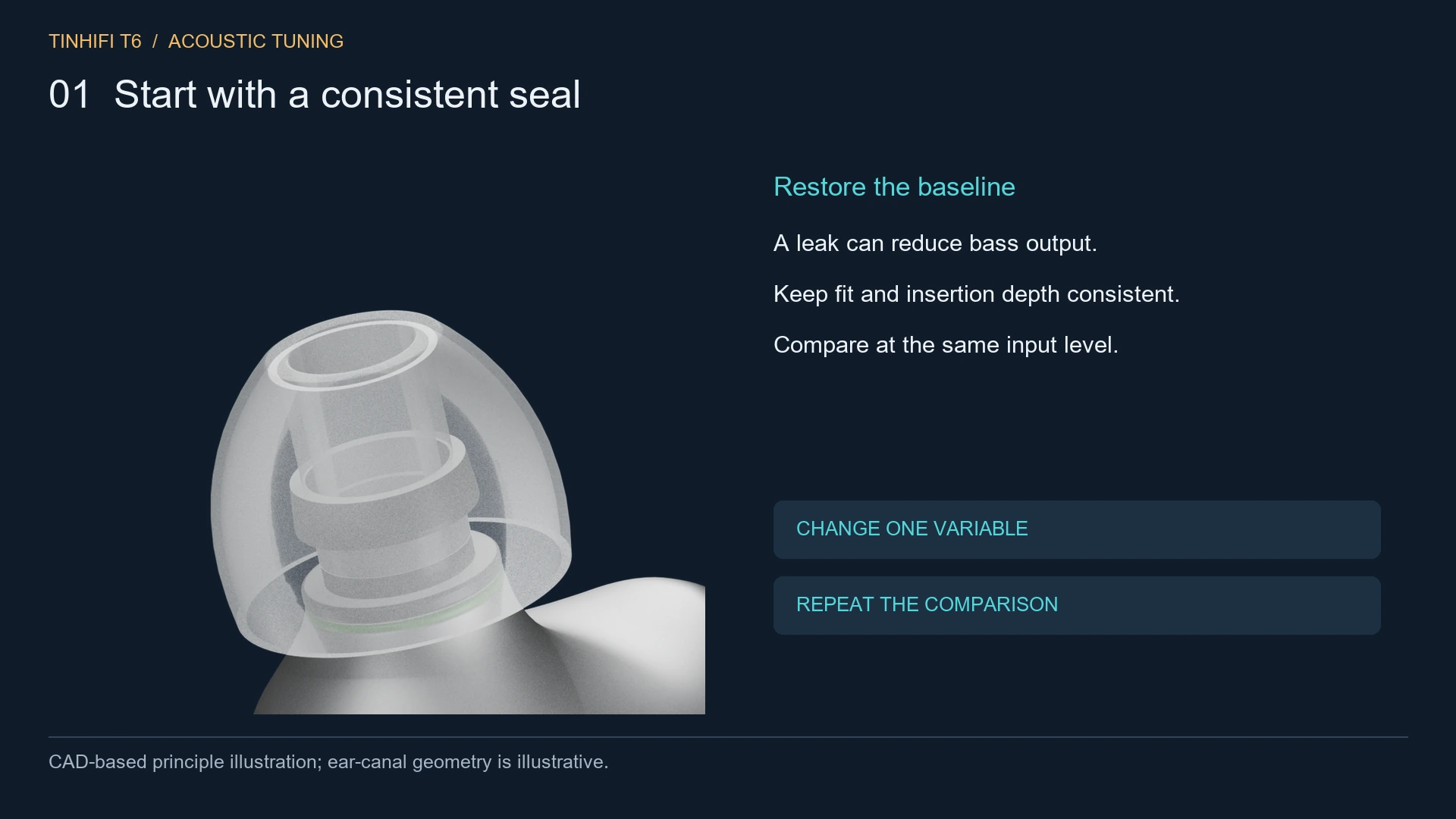
If the bass changes when you reseat an earphone, fix the fit first. Try an appropriate ear-tip size, keep the insertion comfortable and repeat the comparison. A leak between the tip and ear canal can reduce low-frequency output. Shure’s fitting instructions identify an inadequate seal as a cause of missing bass.
For development, record the tip, nozzle, source and insertion method before comparing prototypes. Keep those choices fixed. Otherwise, a fit change can be mistaken for an improvement from a new damping mesh.
Then define what “more bass” means. Is the missing quality the deep rumble beneath an electronic track, the body of a kick drum, or the weight of a bass guitar? These overlap, but a broad boost does not answer all three equally well.
2. Adjust the front APC damping as a controlled experiment
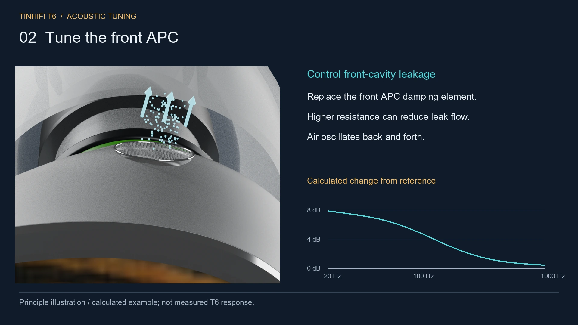
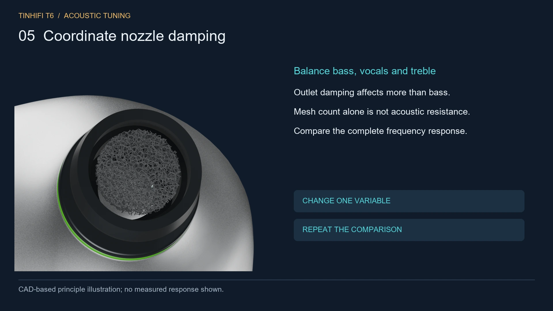
The T6 engineering reference supplied for this article identifies the round mesh beneath the ear tip as the front-cavity APC damping component. It is separate from the sound outlet. The confirmed reference channel is 0.9 mm in diameter; that number does not describe the diameter of the visible mesh or establish its acoustic resistance.
A front vent provides an acoustic leakage path. Changing its resistance changes the load seen by the driver and ear canal. In a simplified low-frequency model, greater resistance can reduce leakage and increase low-frequency pressure. That is a conditional result, not a rule that the densest mesh produces the best sound. COMSOL’s ear model illustrates why vent leakage and narrow-channel losses matter.
An engineer would compare specified damping parts while keeping the remaining assembly unchanged. The checks include response, repeatability and pressure behaviour. Mesh appearance alone is not a reliable resistance specification, and fully sealing the opening is not equivalent to fitting a controlled acoustic damper.
3. Tune the rear vent together with the driver
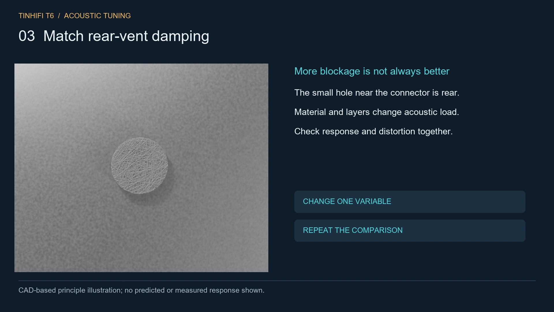
The small opening beside the cable connector is the rear pressure vent in the confirmed T6 reference. It serves a different cavity from the front APC opening. The two should not be treated as interchangeable bass controls.
Changing the rear vent or its damping changes the acoustic load behind the diaphragm. The result depends on the driver, cavity and other leakage paths. It can alter the low-frequency response and resonance behaviour; it does not support a universal “smaller hole means better bass” prescription.
For a bass-focused prototype, compare one rear-vent configuration at a time and keep the front APC part fixed. Listen for unwanted noises as well as tonal differences, and check the response at more than one playback level. A heavier kick is not an improvement if it comes with rattling or a response that varies substantially between samples.
4. Treat rear-cavity volume as an air spring
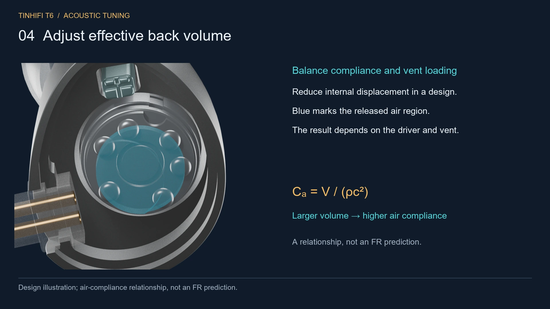
In a simple enclosed-volume model, acoustic compliance is proportional to volume:
Cₐ = V / (ρc²)
Here, V is the air volume, ρ is air density and c is sound speed. More volume means greater compliance: the enclosed air is less stiff. COMSOL’s lumped speaker documentation describes this low-frequency approximation.
That relationship helps explain a design change; it does not predict the T6’s complete response. A vented cavity also has resistance and inertance, while the driver contributes its own moving mass, suspension and losses. Enlarging a chamber is therefore not a guaranteed bass upgrade.
This is a development decision about internal geometry. A CAD comparison can show the available space and a proposed volume change, but the final response needs a physical prototype. Shell size alone cannot tell a listener how deep or controlled the bass will sound.
5. Recheck vocals, nozzles and the hybrid balance
Once the low end changes, return to a familiar vocal recording. Does the singer still sound natural? Can you follow the bass line beneath the voice? Does a kick drum have a distinct attack, or has the whole mix simply become heavier?
The T6’s interchangeable nozzles give users a manufacturer-provided tuning option. In development, outlet damping and the combined driver response also need evaluation. Do not assume a nozzle changes only treble, or that a planar driver automatically guarantees transparent highs.
A bass-focused version should earn its extra weight through the whole balance. Simply reducing the upper frequencies may make bass more prominent in relative terms without increasing its output. Likewise, making the treble brighter is not proof that detail lost under a heavy bass balance has been recovered.
6. Compare the finished result at a matched level
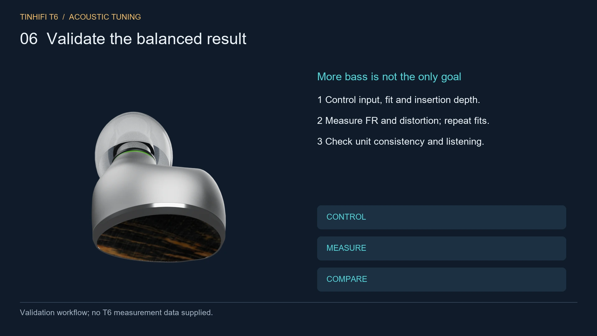
Keep an unchanged reference pair alongside each candidate. Use the same source, tips and nozzle, document reseating, and define the level-matching method. Do not let a louder overall presentation decide the result.
Frequency response is one check. Distortion at relevant output levels, left/right agreement and variation across units also matter. Driver behaviour can become nonlinear at larger excursions; COMSOL’s driver-modelling guide explains why suspension, motor and damping behaviour belong in that assessment.
For listening, choose passages with a sustained low note, a kick and bass playing together, and a voice over a busy arrangement. Record the passage and the observation. “The kick has more weight, but the following bass notes blur together” is more useful than a score labelled “better bass.”
What can a T6 owner try without changing the hardware?
Start with fit and the supplied tuning options, following the manufacturer’s instructions. If your playback app supports EQ, a modest low-shelf adjustment is a reversible way to explore your preference. Leave digital headroom when adding boost: REW’s EQ documentation distinguishes the filter response from the measured response and reports required headroom.
There is no validated T6 bass EQ preset in this article. Avoid using large boosts to compensate for a poor seal, and do not treat front or rear vents as openings to tape shut. An engineering damping comparison is a different operation from an improvised modification.
Why retain a balanced T6 tuning?
Some listeners want a stronger physical impression from drums and electronic bass. Others want less bass prominence across long sessions or vocal-led music. TINHIFI’s stated preference for balance gives the development team a direction; it does not establish one setting as the right answer for every listener. The brand discusses that intention in its balance statement.
The useful engineering challenge is to add the weight a listener wants while keeping the rest of the recording intelligible and the product consistent. A more bass-focused variation can serve that audience without replacing the balanced version’s purpose.
If you could choose the next tuning direction, would you want deeper sub-bass, more kick-drum weight, or the current balance? Tell us which track makes the difference for you.
Technical basis: TINHIFI-supplied design references and the sources linked above. CAD geometry, principle diagrams and calculated examples are distinct from measured product performance.