
Sound in the Real World: The Physics Every Audio Builder Uses
A simple explanation first, then a practical way to use the idea when you listen, compare or create an IEM.
Local status: original English rewrite for review only; not published.
Original English manuscript
Acoustics is not a collection of exotic formulas. It is the working language behind an IEM seal, a speaker cabinet, a noisy air-conditioning duct and a concert hall. It asks three connected questions: how sound is created, how it travels, and how a listener receives it.
This first chapter builds the physical foundation for the rest of the guide. The aim is practical: understand what a measurement means, predict what a room or product will do, and recognise the mistakes that a curve alone cannot reveal.
1.1 Sound is motion passed through a material
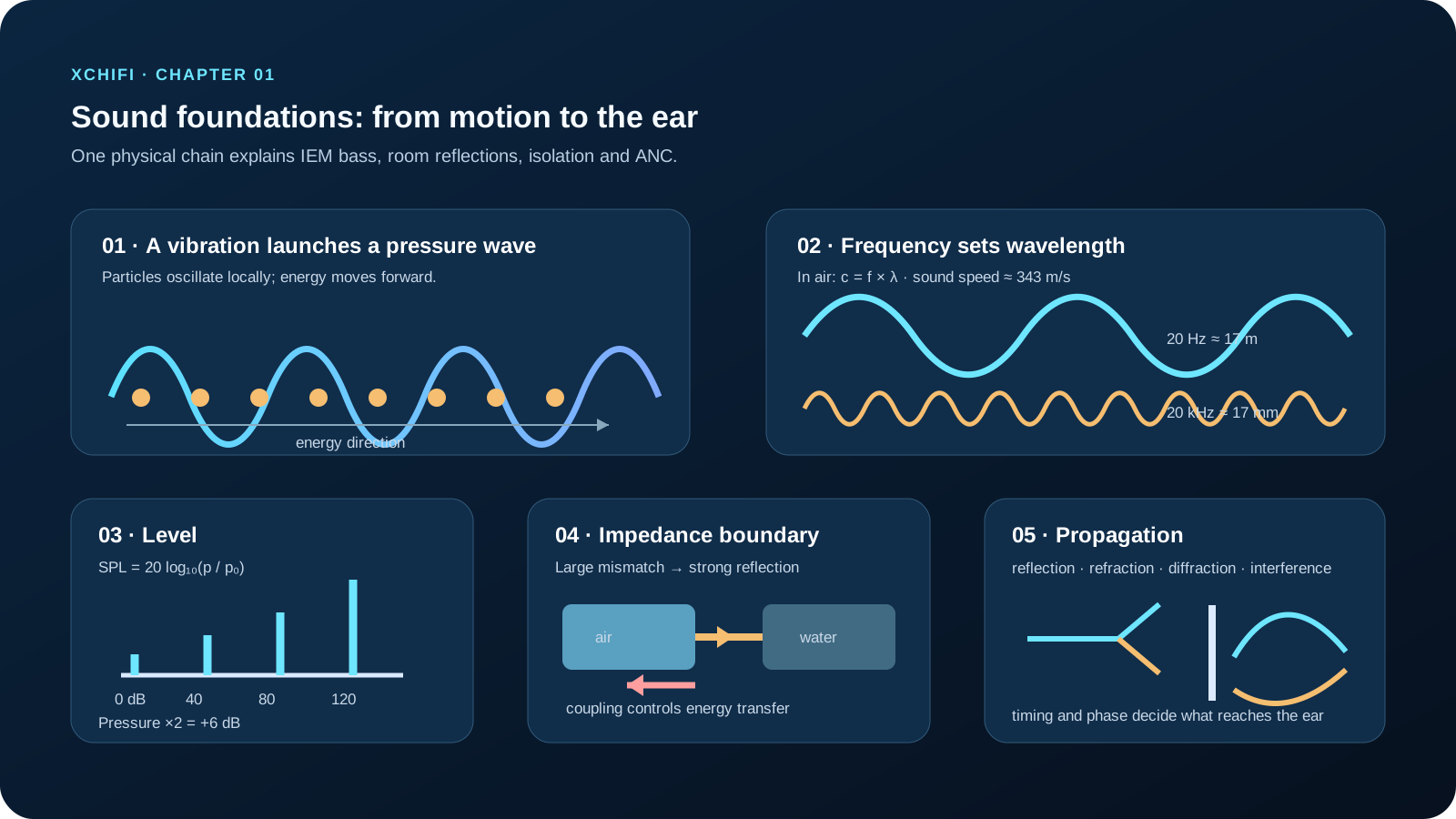
A sound wave begins when something moves. Strike a desk, and its surface vibrates. It compresses the air immediately next to it; that compressed air pushes the next layer of air; the pattern continues outward. The air particles do not travel from the desk to the listener. They move back and forth around their average positions while carrying energy and pressure variation onward.
In air and liquids, ordinary audible sound is mainly a longitudinal wave: the local particle motion is broadly parallel to the direction in which the wave travels. That differs from the up-and-down transverse motion often drawn on a rope. The familiar sine-wave plot is usually a graph of pressure or displacement against position or time—not a literal picture of air moving up and down.
Sound needs a medium. A loudspeaker placed in a vacuum may still have a moving cone, but there is no air to transmit its motion to your ear. This simple fact also explains why coupling between materials matters so much: sound travels through air, plastic, metal and tissue in very different ways.
Engineering habit: when a product buzzes, first ask what is vibrating and what it is coupled to. A loose grille, cable, enclosure wall or desk can become part of the sound system even when it was never intended to be one.
1.2 Frequency and wavelength set the scale of the problem
Frequency tells us how many cycles occur each second, in hertz (Hz). It is strongly related to perceived pitch. Wavelength tells us the physical length of one cycle. Their relationship is:
`c = f × λ`
Here, `c` is sound speed, `f` is frequency and `λ` is wavelength. At room temperature, sound in air travels at roughly 343 m/s.
| Frequency band | Approximate wavelength in air | Why it matters |
| — | —: | — |
| 20–200 Hz | 17.2–1.72 m | Room modes, sub-bass, machinery noise |
| 200–2,000 Hz | 1.72 m–17.2 cm | Voice, many instrument fundamentals |
| 2,000–20,000 Hz | 17.2–1.7 cm | Treble detail, directivity, small features |
A 20 Hz wave is about 17 metres long. That scale explains why low-frequency control needs room volume, mass, distance or carefully designed resonant treatment; a thin decorative panel rarely changes it much. At 20 kHz, one wavelength is only about 17 mm, so small nozzle features, grille openings and reflections close to an IEM driver can matter.
Wavelength also predicts diffraction. A wave bends most easily around an obstacle when the obstacle is comparable to or smaller than its wavelength. Long bass waves can wrap around a barrier more readily; short treble waves are more directional. Gaps are their own problem: an unsealed gap leaks sound, and a high-frequency path can remain obvious even when the rest of a wall is heavy.
1.3 Sound pressure, intensity and decibels
Sound pressure is the tiny alternating pressure change around normal atmospheric pressure. We express sound-pressure level as:
`SPL = 20 × log10(p / p₀)`
where `p₀` is 20 micropascals in air, the conventional reference pressure near the threshold of hearing. 0 dB SPL is not no sound. It is a reference level. Human hearing spans an enormous range of pressure, so the logarithmic decibel scale is practical.
Sound intensity describes energy flow per unit area, measured in watts per square metre. In a simple plane travelling wave, intensity is proportional to the square of RMS pressure:
`I = p² / (ρc)`
where `ρc` is the characteristic acoustic impedance of the medium. Pressure and intensity are related, but they are not interchangeable. In the same medium, doubling pressure is approximately +6 dB SPL; doubling intensity is +3 dB. Mixing those rules produces errors quickly.
Practical check: label every plot with its quantity and reference. “dB” alone does not say whether the result is dB SPL, dBFS, dBV, a normalised response, or an intensity level. A correct calculation with an unclear reference is still a misleading result.
1.4 Acoustic impedance: why boundaries reflect sound
Acoustic impedance describes how a medium relates pressure to particle velocity. For a simple travelling wave, its characteristic value is approximately:
`Z = ρc`
Air is around 415 Rayl, water is roughly 1.5 million Rayl, and steel is much higher again. At a large impedance mismatch, most acoustic energy reflects at the boundary. An airborne sound trying to enter water couples very poorly; that does not mean fish cannot hear—they hear underwater sound very well—but it does mean an ordinary airborne loudspeaker is an inefficient underwater transmitter.
Impedance matching is a design tool. Ear tips create a seal and an acoustic load for an IEM. A horn can match a driver to air more efficiently. A hydrophone or underwater projector uses materials and geometry suited to water. In every case, the question is the same: where does the energy go at the boundary?
1.5 What happens as sound travels
#### 1.5.1 Reflection: useful energy, badly timed energy
Hard surfaces reflect more sound than soft porous surfaces. The basic geometric model follows the familiar rule that angle of reflection equals angle of incidence, though real surfaces scatter and absorb at the same time.
In a room, the arrival time and strength of reflections decide whether they add spaciousness, clarity problems or a distinct echo. A delay around tens of milliseconds can blend with the direct sound; a stronger, later reflection can become audible as a separate repeat. The threshold depends on programme material, level and room context, so “one fixed echo time” is not a reliable design rule.
Do not cover every surface with absorption. A fully dead room can feel unnatural and make musical monitoring difficult. Good room work balances early-reflection control, low-frequency management, diffusion and the intended use of the space.
#### 1.5.2 Refraction: sound bends when sound speed changes
Sound bends when one part of the wavefront travels faster than another. Temperature gradients in outdoor air are a common example. On a sunny day, warmer air near the ground often makes sound speed higher near the ground, bending rays upward. Under a night-time temperature inversion, cooler air sits low and speed increases with height, tending to bend sound downward and sometimes making distant sources unusually audible.
Wind gradients, humidity and large temperature differences can reinforce or complicate this behaviour. For outdoor prediction, the message is simple: the atmosphere is part of the acoustic system.
#### 1.5.3 Diffraction: why barriers never act like walls on a drawing
Sound can bend around edges. The effect grows when wavelength is large compared with the obstacle. That is why a barrier can leave a low-frequency rumble even when it blocks a clear line of sight, while a small leak or open door can ruin high-frequency isolation.
For isolation, start with continuity: seal gaps, avoid rigid bridges, and treat service penetrations. Then add mass, decoupling or a purpose-built silencer according to the actual transmission path. A heavy wall with a poor door is only as good as the door.
#### 1.5.4 Interference: addition, cancellation and control
When waves meet, their pressures add. In phase, they reinforce; out of phase, they reduce one another. Interference can create comb filtering from reflections, standing-wave patterns in rooms, and useful cancellation in active noise control.
ANC works only when its anti-noise arrives with the right timing, level and phase at the listener’s ear. It is therefore most effective where the system can predict the noise and control the acoustic path—usually low-frequency, repeatable noise. A tiny delay or fit change can reduce the result, which is why passive isolation and fit remain essential.
Chapter map: from physics to decisions
The ideas in this chapter connect in a practical order:
1. A vibrating object launches pressure changes into a medium.
2. Frequency and wavelength set the physical scale of those changes.
3. Pressure, intensity and decibels describe their level with defined references.
4. Impedance determines what happens when sound meets a new material.
5. Reflection, refraction, diffraction and interference determine what reaches the listener.
When you can move through that chain, you can reason about an IEM nozzle, a room reflection, an ANC result or a noise barrier without relying on slogans. The next chapters add the listener, the transducer and the measurement system to this physical foundation.
Visual brief
Create an original XCHIFI dark-navy learning graphic with five labelled panels: longitudinal compression/rarefaction in air; a 20 Hz versus 20 kHz wavelength scale; an SPL reference ladder; an air-to-water impedance boundary with reflected energy; and four small propagation sketches for reflection, refraction, diffraction and anti-phase cancellation. Use clean English labels and no copied diagrams.