
The Parts That Translate Between Electricity and Sound
A simple explanation first, then a practical way to use the idea when you listen, compare or create an IEM.
Local status: original English rewrite for review only; not published.
Original English manuscript
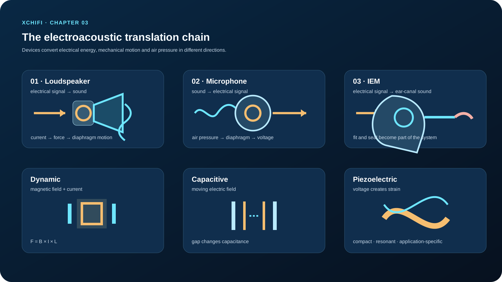
Every audio product has at least one translator. A loudspeaker turns an electrical signal into moving air. A microphone turns moving air into an electrical signal. A headphone does both jobs at once in a small, highly personal acoustic space.
This chapter gives a practical map of electroacoustic devices: what category a product belongs to, how its transducer works, which specifications matter, and how to select it for a real use case instead of a marketing comparison.
3.1 Three families of electroacoustic devices
The most useful first classification is by the direction of conversion.
3.1.1 Loudspeakers: electricity to sound
A loudspeaker receives an electrical signal, creates mechanical motion, then uses a diaphragm to create pressure changes in air. The familiar dynamic driver uses a voice coil moving in a magnetic gap. It remains common because it can produce substantial excursion, works across a wide range of sizes and offers a good balance of efficiency, bandwidth and cost.
Electrostatic loudspeakers use a very light charged diaphragm between stators. Their low moving mass can support excellent high-frequency behaviour, but they need high bias voltage and special drive electronics. Piezoelectric elements deform when voltage is applied; they are mechanically simple and useful in buzzers, alarms and ultrasonic applications, but their response and distortion characteristics make them a less universal choice for high-fidelity full-range reproduction.
Do not judge a driver by technology alone. A dynamic driver can be superb or poor; an electrostatic panel can be transparent but impractical for a portable product. The acoustic load, enclosure, crossover and intended level decide the result.
3.1.2 Microphones: sound to electricity
A microphone reverses the direction. Incoming pressure moves a diaphragm, and the capsule converts that motion into a voltage or digital signal.
- Dynamic microphones are rugged, tolerate high sound-pressure levels and often suit stage work.
- Condenser microphones use a charged capacitor capsule. They are commonly sensitive and detailed, but require powering and benefit from sensible environmental control.
- MEMS microphones are tiny silicon-based devices used extensively in phones, earbuds and arrays. Their size and manufacturing consistency make them valuable for compact products.
The capsule is only half the choice. Directional pattern, self-noise, handling noise, wind protection, placement and room reflections can change a recording more than a small difference in catalogue frequency response.
3.1.3 Headphones: loudspeakers coupled to a human ear
Headphones are miniature loudspeaker systems, but their acoustic load is unusually variable because it includes the head, ear, ear canal, ear tips and fit.
An IEM uses the ear canal as part of the acoustic system. A stable seal can make deep bass easier to reproduce and improves isolation, while a small leak can remove much of the low-frequency output. Over-ear designs use a larger enclosed or open volume; they can provide a different spatial presentation, but open designs leak sound and admit environmental noise. Bone-conduction products transmit vibration through the skull rather than relying on ear-canal air pressure, which can be useful in awareness-focused designs but involves different bandwidth, distortion and fit constraints.
3.2 Three core transduction mechanisms
Technologies differ because they convert energy in different ways. Understanding the mechanism makes specifications easier to interpret.
3.2.1 Electrodynamic transduction: current in a magnetic field
A conductor carrying current in a magnetic field experiences force. In a simplified voice-coil system:
`F = B × I × L`
`B` is magnetic flux density, `I` is current and `L` is the active conductor length inside the field. The coil is attached to a diaphragm, so changing audio current produces motion and then sound. In a microphone, diaphragm motion moves the coil through the field and generates a voltage in the opposite direction.
The formula is only the opening move. Useful driver design also needs a stable magnetic gap, a light but controlled moving assembly, suspension compliance, heat handling and a diaphragm that does not break into unwanted modes. A larger magnet by itself does not guarantee better bass; motor strength, moving mass, enclosure and excursion all interact.
3.2.2 Capacitive and electrostatic transduction: a moving electric field
A capacitor contains two conductors separated by an insulating gap. If one element moves, capacitance changes. In a condenser microphone, a polarised diaphragm and backplate turn pressure-driven motion into a varying electrical signal. In an electrostatic loudspeaker, a charged diaphragm is attracted and repelled by driven stators.
The attraction of capacitive systems is low moving mass. Their engineering cost is sensitivity to gap geometry, bias voltage, humidity, contamination and high-voltage safety. A poor environment can raise leakage or noise; a careful implementation can deliver very fine detail.
3.2.3 Piezoelectric transduction: voltage becomes strain
Piezoelectric materials produce charge when mechanically stressed and deform when voltage is applied. That reversible behaviour makes them useful for alarms, contact sensors, ultrasonic emitters and specialised high-frequency drivers.
Their strengths are compactness, simple construction and high voltage sensitivity. Their limits include nonlinearity, resonant behaviour and a response that often needs deliberate mechanical or electrical shaping. A piezo component is not automatically “bad”; it is a tool whose operating range must match the task.
3.3 Specifications that deserve context
A specification is useful only when its condition is stated. Start with these five, then ask how each was measured.
| Specification | What it actually tells you | Questions to ask |
| — | — | — |
| Sensitivity | Output for a stated input | Was it measured at 1 W, 2.83 V, 1 m, or at the ear? |
| Frequency response | Level versus frequency in a fixture | What smoothing, target, level and placement were used? |
| Impedance | The electrical load over frequency | What is the minimum impedance and phase, not only the nominal value? |
| Distortion | Added harmonic or intermodulation content | At which frequency and output level? |
| Power handling | A thermal/mechanical operating limit | Is it continuous, short-term, or limited by excursion? |
For a conventional loudspeaker, sensitivity might be expressed as dB SPL at 1 m for 1 W or 2.83 V. For an IEM, efficiency and sensitivity use different fixtures and can be strongly affected by seal. Frequency range should never be read as a quality score: a product can claim 20 Hz–20 kHz while having large deviations inside that span.
Nominal impedance is especially easy to misuse. An 8-ohm loudspeaker can dip much lower at some frequencies, and a reactive load asks an amplifier for current and voltage at different times. A high sensitivity rating does not guarantee an easy load. Read the impedance curve and amplifier capability together.
3.4 A working mental model
Keep the chapter organised in three layers:
1. Device family: speaker, microphone or headphone—what direction does energy travel?
2. Transduction mechanism: electrodynamic, capacitive/electrostatic or piezoelectric—what creates motion or voltage?
3. System behaviour: sensitivity, response, impedance, distortion and power handling—how does this particular implementation behave in use?
The fourth layer is the one data sheets cannot finish: application context. A conference microphone needs controlled pickup and feedback resistance. A portable IEM needs seal stability, low noise and appropriate drive. A public-address driver needs output and reliability at its intended coverage pattern.
3.5 A three-step selection method
Step 1: define the use. Is the product indoors or outdoors? Is the priority speech intelligibility, music, monitoring, isolation, battery life or maximum output? What size, cost, weather and safety limits apply?
Step 2: compare the relevant evidence. Use the measurement conditions, not just headline figures. Match amplifier capability to the actual impedance load. Check response, distortion and thermal limits at the level the product will actually use.
Step 3: validate in the real system. Listen and measure after integration. A meeting microphone with excellent self-noise can still fail if its pickup pattern captures too much room reflection. An IEM driver that looks ideal on a coupler can change character when fit, venting and nozzle geometry change.
Pink noise can be useful for finding broad tonal or coverage issues because it carries equal energy per octave. Sweeps and music reveal different problems. No single test signal replaces controlled listening, and controlled listening does not replace measurement.
The point of electroacoustic engineering is not to find a universally best device. It is to choose a transducer whose physical behaviour serves the listener, the environment and the product around it.
Visual brief
Create an original XCHIFI dark-navy educational diagram titled “The electroacoustic translation chain”. Show three large, clearly separated paths: electrical signal → dynamic speaker → air pressure; air pressure → condenser/MEMS microphone → electrical signal; electrical signal → IEM driver → ear canal. Add a second row comparing electrodynamic, capacitive and piezoelectric mechanisms with simple cross-sections. Use clean English labels and no copied product imagery.