
SOURCE 01 · FOUNDATIONS · 01 / 17
Fundamentals of Acoustics & Physical Principles for IEMs
The physical foundation of an IEM: how a diaphragm creates a sound wave, why frequency and wavelength matter, how sound pressure is measured, and how impedance and wave behaviour shape a tiny acoustic path.
1.1 The nature of sound
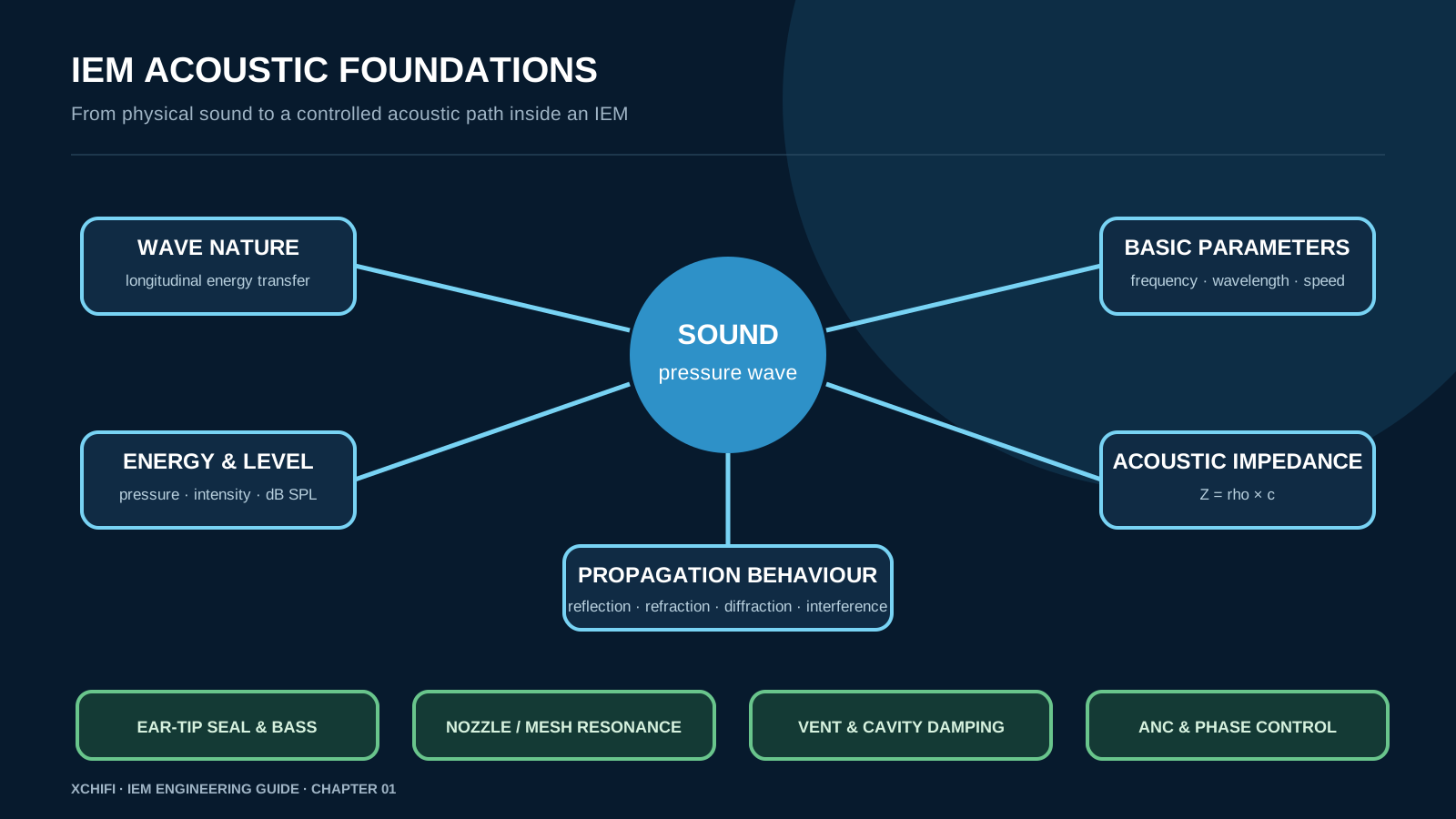
Sound is a mechanical disturbance travelling through a medium. In an IEM, the diaphragm moves and passes energy through the air in the front chamber, nozzle and ear canal. The air molecules do not travel from the driver to the eardrum as a stream; each small volume moves back and forth and passes the pressure change onward. This is a longitudinal wave: particle motion and sound propagation follow the same axis. With no medium, such as a vacuum, this mechanical hand-off cannot occur.
1.2 Frequency and wavelength
Frequency tells us how many cycles happen each second and is measured in hertz. Wavelength is the physical length of one cycle. They are linked by c = f x lambda, where c is sound speed, roughly 343 m/s in air. A 20 Hz wave is about 17 metres long, while a 20 kHz wave is only about 17 millimetres long. This scale difference explains why IEM bass depends on moving enough air and sealing the ear, while high-frequency response is strongly affected by millimetres of nozzle, mesh and insertion depth.
1.3 Sound pressure, intensity and decibels
Sound pressure is the small alternating pressure around atmospheric pressure, measured in pascals. Sound intensity describes energy flow per area and is related to the square of pressure. Because the range from hearing threshold to discomfort is enormous, sound-pressure level uses decibels: SPL = 20 log10(p / 20 microPa). Doubling sound pressure adds about 6 dB SPL; doubling intensity adds about 3 dB. These are related quantities, but they are not interchangeable. For IEM work, always state the test level when comparing output or distortion.
1.4 Acoustic impedance
Acoustic impedance describes how strongly a medium or structure resists oscillating air motion. For a simple medium, Z = rho x c: density multiplied by sound speed. In an IEM, impedance is not only a material property. A narrow bore adds acoustic mass, a cavity adds compliance, and a mesh or damper adds resistance. The driver sees their combined load. That is why a small vent, damper or tip-seal change can alter bass, resonance and pressure feeling without changing the driver itself.
1.5.1 Reflection
A sound wave reflects when it meets a boundary with a different acoustic impedance. Large room reflections can become echo or reverberation; inside an IEM, the same principle appears as small cavity and nozzle reflections. Their time scale is much shorter, but they can still reinforce or cancel a narrow frequency region. Geometry and damping decide whether the reflection is useful or distracting.
1.5.2 Refraction
Refraction occurs when sound changes direction because its speed changes across a boundary or gradient. It is more obvious outdoors, where temperature layers bend sound paths, than inside a short IEM nozzle. The useful IEM lesson is that sound speed and medium properties matter: changes in air path, material interfaces and acoustic loading influence where resonances form.
1.5.3 Diffraction
Diffraction is the ability of a wave to bend around an obstacle or spread through an opening. Longer wavelengths bend more readily. This is why low-frequency noise can seem to pass around barriers while shorter high-frequency detail is easier to block. In IEMs, tiny vents and openings must be understood as acoustic paths, not only physical holes.
1.5.4 Interference
When pressure waves meet, they add. In phase, they reinforce; out of phase, they reduce one another. ANC uses controlled destructive interference, but only works when timing, level and the acoustic path are accurately managed. IEM designers also encounter interference in bores, multiple-driver paths and cavity resonances. A stable design controls where those wave paths combine.