
SOURCE 04 · DRIVER DESIGN · 04 / 17
IEM Driver Design & Modelling
A rewrite of driver design and modelling for the much smaller IEM driver: motor, diaphragm, resonance, damping and the volumes around it.
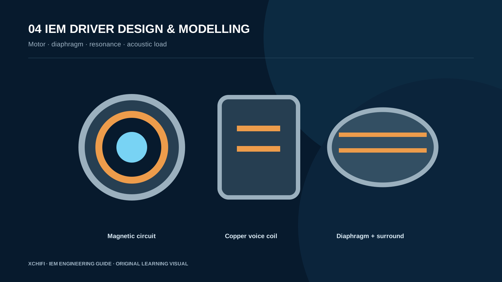
4.1 IEM driver structure
Diaphragm, voice coil and suspension move together; magnet, top plate and gap form the motor. Their mass, stiffness and force factor determine control around resonance.
4.2 Resonance and T/S-style parameters
The diaphragm, suspension and trapped air form a spring-and-mass system. Too little damping can make bass loose; too much reduces output and efficiency.
4.3 Equivalent-circuit thinking
Resonance, total Q, moving mass, compliance, motor strength and coil resistance describe the driver. In an IEM, front volume, rear chamber, vent and tip become part of the final load.
4.4 Sealed and vented IEM acoustic loading
Nozzle and front volume form the route to the ear; rear volume and vent affect damping, bass and pressure. The shell is acoustic engineering, not merely styling.
4.5 IEM driver design summary
Electrical resistance, mechanical mass and compliance, plus acoustic mass and resistance, can be treated as a connected system. This makes a vented IEM easier to reason about than a collection of isolated parts.